Looking for a SmartShunt wiring diagram?
Use Victron’s official installation diagrams for the standard battery connection, auxiliary input and GX connection. The manufacturer’s drawings—not an illustrative product image—are the installation reference.
Terminal connections · Configuration instructions · Troubleshooting
Before You Start
This guide is for the standard SmartShunt 500A. Check your bank voltage, maximum current, cable requirements and mounting location against the exact model manual. For our experience aboard, read the SmartShunt review.
You will need:
- SmartShunt matched to the system, with its supplied fused leads
- Battery cable, lugs and crimping tools selected for the installation—not a universal cable gauge
- Suitable mounting hardware and a calibrated torque wrench
- Optional VE.Direct cable if connecting to a GX device
SmartShunt terminal connections
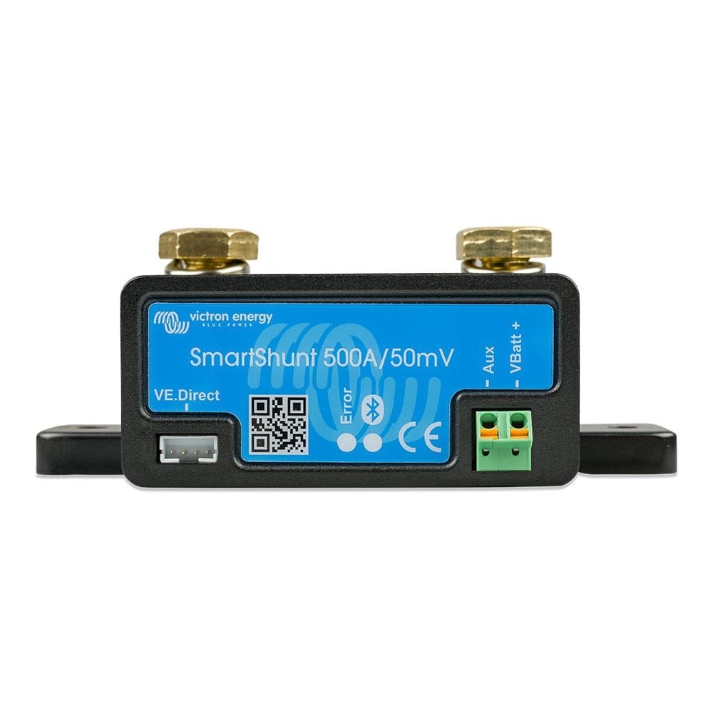
The SmartShunt has two sides: BATTERY and SYSTEM.
- BATTERY MINUS: battery-bank negative only.
- SYSTEM MINUS: the negative returns for loads and charging sources on the monitored bank.
Do not change engine grounding, bonding or starter arrangements from this summary. Have a qualified marine electrician resolve any uncertainty about the complete system.
This is the most important concept. If any negative wire connects directly to the battery negative post instead of going through the shunt, those amps are invisible to the monitor. Your state of charge will drift and become inaccurate.
Older units may label SYSTEM MINUS as LOAD MINUS. Match the labels to Victron’s connection overview and installation procedure, not just the unit’s orientation in a photograph.
Step by Step
1. Disconnect the Battery
Isolate charging sources and loads, and make the installation safe using the battery and equipment manufacturers’ shutdown procedures. Do not work on energized battery wiring. If the grounding or isolation arrangement is unclear, use a qualified marine electrician.
2. Mount the Shunt
Mount the standard IP21 SmartShunt in a dry place. Its mounting holes are 5.5 mm; mounting screws are not included. Check the exact model’s dimensional drawing before choosing hardware.
3. Wire the Battery Side
Connect battery-bank negative to BATTERY MINUS with a properly sized battery cable and suitable lugs. Size cables for the actual system current, run and installation conditions; do not infer a cable size from the shunt’s 500A rating alone.
Use correctly crimped lugs. For the 500A model, Victron specifies a maximum shunt-terminal torque of 21 Nm. Follow the manual rather than judging tightness by feel.
4. Wire the System Side
Connect SYSTEM MINUS to the monitored system’s negative bus. The load and charging-source returns belong on that side so their current is measured. Use the full system diagram to account for every return path before moving existing wiring.
5. Connect the Sense Wire
Connect the supplied fused red lead’s ferrule to Vbatt+ and its ring terminal to battery positive, following Victron’s connection sequence. Retain the fuse.
6. Optional GX Connection
A separate VE.Direct cable connects the shunt to a Cerbo GX or another compatible GX device. A GX Touch is the display for a GX device, not a direct shunt connection. Bluetooth-only operation needs no VE.Direct cable.
7. Reconnect and Configure
Restore power using the equipment manufacturers’ procedures. Then follow Victron’s configuration instructions: battery capacity, charged voltage and synchronization must suit your bank. Confirm discharge reads negative and charging reads positive.
Common Mistakes
- Loads or chargers returning directly to battery negative bypass measurement. Keep their returns on SYSTEM MINUS.
- Do not redesign engine grounding or starter circuits from this overview. Follow the appropriate system diagram.
- The auxiliary input can monitor a second battery’s voltage. It does not measure that battery’s state of charge; follow Victron’s auxiliary-input wiring instructions.
- Incorrect configuration or a bypassed shunt can make the state-of-charge reading misleading.
Verifying It Works
With charging sources inactive, turn a known load on and off and check the change in current. Discharge should read negative; charging should read positive. Other active loads affect the total.
A falling charge current alone does not trigger 100% synchronization. The configured charged-voltage and tail-current conditions must both be met for the configured detection time. See Victron’s synchronization explanation and choose settings appropriate for your battery.
A bypassed shunt is one possible cause of missing current, not the only explanation for a bad reading. Incorrect battery settings and failure to synchronize can also produce state-of-charge drift. Follow Victron’s troubleshooting checks before changing wiring or recalibrating.
→ Victron SmartShunt 500A on Dupree Products
Related Articles
- Best Marine Battery Monitor: Victron SmartShunt 500A
- RV Battery Monitoring: What Actually Works
- RV Solar System Sizing
Free Tools
These calculators can help with preliminary wire and fuse sizing. They do not replace the equipment instructions or a check of the complete installation:
- Marine Wire Gauge Calculator — sizes any DC wire run for ABYC voltage drop and ampacity requirements
- Marine Fuse Sizing Calculator — recommends fuses with proper continuous/motor multipliers and warns if your wire can't safely handle the fuse